meta data for this page
Geometry forces
When you need scene geometry to control anything about your model then you’ll need to take advantage of Geometry Forces. Example scenarios include vines crawling on a fence, a building preventing tree branches from growing near it, and roots growing in and around each other without intersecting. Geometry Forces are accessed just like all of the other forces (“Geometry” is just another type of force like Direction, Magnet, etc.) and perform the following tasks.
- Identify the geometry to be used (either a mesh asset or parts of the model itself)
- Position it in the scene (if it’s a mesh asset, model parts remain where they are)
- Embed it in the output (if it’s a mesh asset, model parts already are)
- Specify how things behave around the geometry (attracted to it, avoid it, ignore it, etc.)
- Specify what happens if anything hits the geometry (crawl around it, stop, etc.)
- Set the range around the geometry where it has an effect
Please refer to the sample model named “Geometry Forces/Geometry_Forces_Example.spm” for this section of the documentation. This sample model demonstrates how to use Geometry Forces using very simple models to help make a complicated topic a bit easier to comprehend.
Note: Collections were a technique used in version 8 and earlier to allow procedurally generated geometry to be routed through the mesh asset system for use with forces. This system has now been replaced by Geometry Forces. Earlier models that used collections will be automatically upgraded to the Geometry Force approach when loaded in version 9. Such models may require touching up to complete the process.
Adding a geometry force
Geometry Forces are added just like any other force. Use the toolbar force button, right click in the Tree Window, or click the forces icon in the Generation Editor and select:
“Add force→Geometry→No specified mesh”
This will add an empty Geometry Force to your scene.
Assigning geometry
Geometry Forces can use mesh data from two sources: mesh assets (imported models) or generators (meshes created by the procedural modeler).
Mesh assets
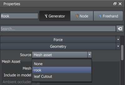
Create a mesh asset by importing a model. In the sample mentioned above we’ve used a simple model of a rook from a Chess set. Select the Geometry Force and do the following to use it.
- Change the property “Geometry:Source” to “Mesh Asset”
- Select your mesh asset with the property “Geometry:Mesh Asset:Mesh”
If you’re using a mesh asset, you can assign a material to it, embed it in the model, and transform it with the scene gizmo using the other properties in the “Geometry:Mesh Asset” group.
Generators
When using generators as the source you can select as many of the generators to contribute geometry to the force as you’d like.
- Change the property “Geometry:Source” to “Generators”
- Use the “Geometry Force actions” menu in the Generation Editor to assign generators to the new force
If you’re using generators, this geometry will update every time the model updates. You don’t need to do anything else. This feature enables you to freely change the model and have other parts of the model update accordingly. You can add or remove generators as you like and you can have as many geometry forces as you need.
Using generators as the source of the geometry requires some special consideration. Please see the final section of this page for more information.
Adding behaviors
“Behaviors” control how Branch generators react to the geometry in the force. Options include:
- Name - A way to identify the behavior later
- Force - How does the geometry affect the branch’s growth?
- Attract (pull towards the geometry or push away, if the value is negative)
- Avoid (if you might hit it, move around it)
- None (ignore it)
- Collide - What happens when the branch hits it?
- None (nothing, goes right through)
- Obstruct (hits and tries navigate on the surface)
- Prune (chops it off where it hit)
- Stop (stops it where it hit, treating like a full length branch)
Geometry Forces can have multiple behaviors and which one is used is specified per generator. Think of a scene where you have a barn, vines, and a nearby oak tree. The idea behind behaviors is that you have one Geometry Force (the barn), then separate behaviors for things that might interact with it. Vines might be attracted to the barn and crawl along it while oak tree branches might avoid the barn and stop if they hit it.
Using a geometry force
Geometry forces are enabled and disabled just like any other force. Select a generator, navigate to the “Forces” group, and enable the geometry force in the list. Below is a screenshot of the “Single Vine” generator enabling the Geometry Force named “Rook”.
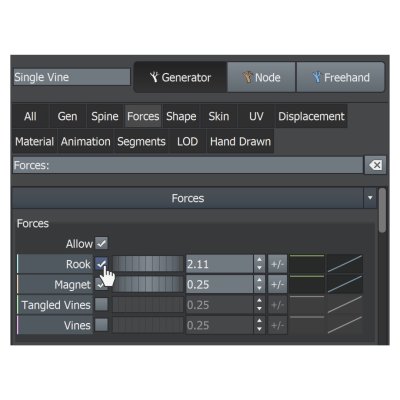
The value of the property is multiplied by the Geometry Force’s strength value and applied to the branch. If more than one behavior has been assigned to the Geometry Force, choose the desired behavior by clicking the name field on the force property and selecting it by name. The parent curve and profile curve can be used to change the force’s influence on the branch in the same manner as any other property.
In the example above, the Geometry Force named “Rook” is being used to attract and obstruct the vine. This setup is very common. The “Attract” behavior pulls the vines toward the Geometry Force according to the strength settings. Then, when it hits, the obstruction aspect of the behavior causes the vine to crawl along the surface.
Once a Geometry Force obstructs any given branch, the properties in the group “Geometry Force Crawling” on the Branch generator (pictured below) control how the branch will crawl over the surface of the geometry.
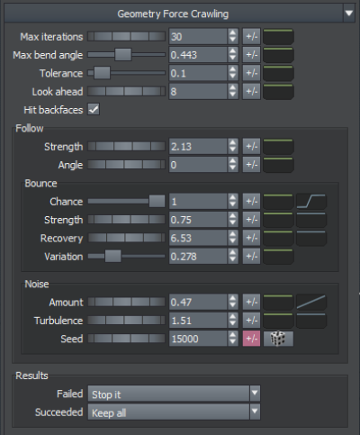
These properties are explained in detail here but the general idea is to use these properties to convey how much the branch can bend (“Max bend angle”), how much of it can press into the mesh (“Tolerance”), how hard it tries to find a solution (“Max iterations”), how much it anticipates what it will need to do (“Look ahead”), and what it will do while it’s touching (“Follow”) group.
Because it’s not always possible to find a solution for placing the branch under these constraints, the “Results” group exists to control how to handle both failures and successes. For example, you may want to throw out any branch that didn’t perfectly crawl along the surface. Or you may choose to just stop it at the point of error.
Note: All force actions and crawling operations are performed simultaneously. Their order in the list of forces does not influence the computation.
Using a geometry force to align
All forces have an “Align strength” property. Any generator that enables a force will combine its own “Forces:Align” settings with the force’s “Align strength” to influence how all nodes are initially oriented. This is different from just making them bend very early; aligning actually changes where they are attached to their parent and in what direction they point.
When a Geometry Force is used to align it will cause nodes to shift away from the geometry as much as possible at their anchor points and point away from the geometry as well. This technique is useful, for example, to ensure ivy leaves do not cut through the wall they are growing. All of the leaves used in the “Vines” example utilize alignment for reference.
Force attenuation
Attenuation applies to Geometry Forces just as it does to any other force type. For Geometry Forces, the distance used is the distance away from the closest point on the geometry’s surface instead of the distance away from the force’s position.
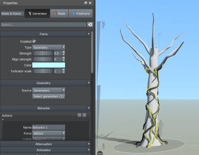
Both “Force:Strength” and “Force:Align strength” can be attenuated, each with their own settings. In the example we’ve been using, the “Rook” Geometry Force does not have its main strength attenuated but does have its align strength attenuated. This technique is used here so that the leaves are free to orient in any fashion until they get very close to the surface of the geometry.
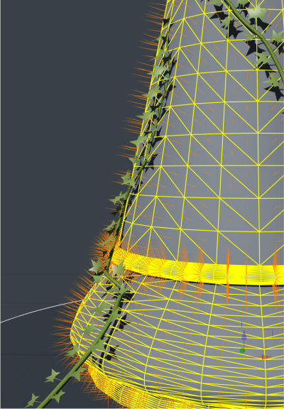
In the screenshot above, the “Rook” geometry force is selected and the orange lines indicate the attenuation distance for alignment attenuation. There is no main force strength attenuation on this force, but, if there were, it would be indicated by similar white lines.
Containers
Similar to attenuation, forces can also have an area of effect controlled by another “container” geometry force, limiting its area of effect. You can indicate an area to be included or excluded for a particular force by setting the corresponding properties in the "Container force" property group to the name(s) of the geometry forces you wish to use as containers.
In the following image, there are four forces: two direction forces and two geometry forces with a sphere mesh indicating the area of effect for the corresponding direction force. The branch is affected by the direction forces in a very precise manner.

Using generators: Compute order matters
If you’re using generators as the geometry source you must take the order in which the generators are computed into account. In general, all of the generators that make up a Geometry Force must be computed before any generator that uses that Geometry Force. The lone exception being that a generator is allowed to use a Geometry Force made from itself (and only itself). This exception allows for things like roots not to intersect with each other even though they’re in the same generator.
The screenshot below is from the sample named “vines_on_tree.spm” in the Geometry Forces sample folder.
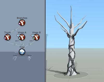
Notice that several of the vines have a “Pass” level shown next to them. Computation is done in passes. Each generator is in the first pass unless otherwise edited. In this example, “Trunk and Branches” are in pass 1 (pass 1 is the default and remains unlabeled). “Vines A” is in pass 2. “Vines B” is in pass 3. The computation order is as follows:
- “Trunk” and “Branches” happen in pass 1. This is done to get the basic tree shape finished. “Vines A” and “Vines B” are ignored in this pass.
- “Vines A” is computed next, in pass 2. It is now free to use the Geometry Force called “Tree” that uses the parts of the model computed in pass 1. The pink circles on the “Trunk” and “Branch” generators indicate they are in the same Geometry Force (you can click on the circle to select the force). It also uses the Geometry Force called “Vines A Force” to make sure the vines don’t collide with themselves.
- “Vines B” is computed next, in pass 3. It uses both of the Geometry Forces that “Vines A” used plus a new one, “Vines B Force”, to again stop self intersections.
You can edit the pass number with the property “Generation:Shared:Pass”. A generator’s pass number will not be allowed to be lower than that of any of its ancestors (it can’t compute until its parent is finished). When making several generators collide against each other, be sure to carefully think about the order in which they need to be computed and make sure the pass numbers reflect that in your model.
Note: Pass errors are detected automatically and an error message is displayed on the generator.